1 Introduction
Thanks for using this Libre Solar charge controller.
The manual describes the usage and most important functions of this specific device. Please visit the Libre Solar website for general information about charge controllers and other devices for DC energy systems.
Read this manual carefully and make sure you understand everything before starting with installation of the charge controller.
Same as the hardware and firmware of the charge controller, also this manual is open source. If you find any error or have suggestions for improvement, please contribute to the repository on GitHub.
1.1 Disclaimer
Due to the fact we are not providing a product in the legal sense, we are also not providing any warranty in any aspect.
The user manual described here has been written and checked with care and to the best of our knowledge.
Libre Solar assumes no liability for the accuracy, completeness or quality of the information provided. Liability claims against the team for material, physical or immaterial damages caused by the use or non-use of the information provided or by the use of incorrect and/or incomplete information are excluded.
All information and instructions are non-binding. Libre Solar reserves the right to change, supplement or delete parts of the pages or the entire document without prior notice.

2 Safety Instructions
The charge controller shall be used only for the intended application.
The maximum voltage and power of the connected solar panel must not exceed the limits of the charge controller. Make sure to consider also the increased voltage of solar panels at low ambient temperatures.
Ensure that the charge controller is configured correctly for the used battery type.
Use lithium ion batteries (e.g. LiFePO4) only if they contain an integrated battery management system (BMS) for additional protection.
Install the device considering general best practices for electrical and mechanical installations in accordance to laws in your country.
An additional fuse must be installed as close to the battery positive terminal as possible.
As sparks can occur during connection of the battery or solar panel wires, don’t install the charge controller close to any flammable materials.
The wire cross-section has to be large enough to handle at least the maximum specified current of the charge controller.
Use insulated tools only.
Fix the wires outside the charge controller to provide a strain relief.
Mount the device vertically on a solid, non-inflammable wall only, with the battery terminals facing downwards.
Keep free space for ventilation next to the device and don’t cover the housing.
3 Description of Functions
The following chapter describes the primary functions of the charge controller. With expert knowledge, the firmware can be adjusted to suit your own needs and implement new features, including different control algorithms, wireless communication interfaces, displays, etc.
3.1 MPPT
This charge controller is a so-called maximum power point tracker (MPPT), which automatically adapts its input voltage to the connected solar panel to extracts as much power as possible.
The MPPT function can only be achieved using a DC/DC converter, which is the core part of the charge controller PCB. It can be recognized by the large inductor and the large electrolytic input and output filter capacitors.
3.2 Three-stage battery charging
The advanced 3-stage battery charging increases life of lead-acid batteries. The setpoints for the different stages are fully configurable via the serial interface and can be adjusted to your system setup.
Bulk stage
The battery is charged with maximum possible current until the topping stage voltage limit is reached. This is the stage where the MPPT algorithm is active.
Topping stage
The batteries are charged for some time using the maximum charge voltage. After a current cutoff limit or a time limit is reached, the charger goes into trickle mode for lead-acid batteries or into standby mode for Li-ion batteries.
This stage is also called absorption mode. In case of Li-ion batteries, this is the constant voltage (CV) charging phase.
Trickle stage
This stage is kept forever for a lead-acid battery and keeps the battery at full state of charge. If too much power is drawn from the battery, the charger automatically goes back to bulk charging stage.
3.3 Load output
In order to protect the battery from deep-discharge, consumers connected to the load ouput are automatically disconnected at low state of charge. As soon as the voltage rises again, the load port is switched back on.
3.4 USB output
The USB port provides power supply for mobile devices like phones. The maximum current per port is 1.5 A, with 2.0 A maximum for both ports.
3.5 Communication interface
This charge controller is equipped with a LS.one port, which incorportates an UART serial interface. It uses the ThingSet communication protocol and allows configuration, monitoring and control of the charge controller.
3.6 Temperature compensation
The battery voltage setpoints for the different charging stages have to be adjusted depending on the battery temperature. The temperature can either be estimated based on temperatures measured inside the charge controller or it can be directly measured at the battery using the external temperature sensor to maximize performance. The external temperature sensor is also connected via the LS.one port.
3.7 LED indicator
The bottom LED close to the USB port indicates if the load output and USB port are enabled. If the light goes off, it means the battery was low and the charge controller protected it from deep-discharging.
The three middle LEDs indicate the state of charge (SOC) of the connected battery. More LEDs means more energy is present in the battery.
The top LED can be freely configured by the firmware developer, e.g. to indicate data transmission.
4 Installation
The following image describes the different terminals and interfaces of the charge controller PCB.
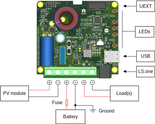
The charge controller features a high-side load switch and should be grounded at the negative battery terminal. There should be no additional grounding of the system. Most important, the wires to the solar panel should not be connected anywhere else except for the charge controller PV input.
4.1 Connection order
Connect the battery to the battery port. As the fuse inside the charge controller cannot protect the wire between battery and charge controller, an additional fuse should be installed close to the poitive battery terminal. Small sparks during connection of the battery are normal and acceptable.
Cover the solar panel and afterwards connect the wires to the PV input terminal.
As a last step, connect the loads like lights, etc. to the load output.
The charge controller is now ready to use.
Disconnection should be done in opposite order.
4.2 Compatible batteries
This charge controller can charge any battery with a nominal voltage of 12 V.
The default settings are safe for all lead-acid batteries, but should be adjusted according to the information provided in the battery datasheet.
For Li-ion batteries you need to configure the voltage setpoints manually using the LS.one serial interface. You must also deactivate the float charging stage.
4.3 Solar modules
The MPPT algorithm can automatically adapt to different types of modules. Any module with 36 to 48 cells in series is suitable. The maximum open circuit voltage even under cold ambient temperature conditions must be below 40 V. Even though the controller automatically derates its power in case of overload, the nominal power under standard test conditions (STC) of the module should not exceed 150 W.
Solar modules need direct sunlight to work properly. Indirect light and partial shading will reduce the performance. Make sure to face the module towards the sun.
Read the datasheet of your solar module for more information about the specifications.
4.4 Mounting
Fix the device vertical at non-flammable surface with the power terminals facing downwards.
The charge controller should be mounted as close to the battery as possible, but avoiding any contact with battery acid or gas emissions.
Never mount the device in a fuel storage compartment, as the fuse can create sparks.
4.5 Wiring and Grounding
The minimum wire cross-section should be 2.5 mm². It is recommended to use 6 mm² wires, which is the maximum the terminals can handle.
The length between charge controller and battery should be less than 1 m.
Use suitable fuses in the wiring harness connected to the load terminal if the cross-section is decreased.
If necessary, only ground the energy system at a single point, which should be at the negative battery terminal.
5 Specifications
| Feature | Value | Comment |
|---|---|---|
| Battery | ||
| Nominal system voltage | 12 V | |
| Maximum voltage | 16 V | |
| Maximum charge current | 10 A | |
| Quiescent current | < 10 mA | |
| PV module input | ||
| Maximum open circuit voltage | 40 V | low temperature to be considered |
| Number of cells per module | 36 to 48 | |
| Maximum short circuit current | 10 A | |
| Maximum nominal power | 150 W | |
| Conversion efficiency | >98% max. | |
| Load output | ||
| Maximum current | 10 A | |
| Switch type | high-side | |
| USB charging port | ||
| Maximum current | 2.0 A | total for both ports |
| Standard settings | ||
| Battery type | Lead-acid | safe general settings, also suitable for LFP |
| Charge algorithm | 3-stage | configurable |
| Topping / absorption voltage | 14.4 V | configurable |
| Trickle charging | 13.8 V | configurable |
| Load disconnect voltage | 11.7 V | configurable, current-compensated |
| Load reconnect voltage | 12.3 V | configurable |
| Temperature compensation | -3 mV/K/cell | configurable |
| Interfaces | ||
| UEXT | I2C, SPI, UART | internal, can be used for displays, etc. |
| LS.one | for external communication | |
| Protection | ||
| Overvoltage | ||
| Undervoltage | ||
| Overcurrent | ||
| PV short circuit | ||
| PV reverse polarity | for max. module open circuit voltage of around 40V | |
| Battery reverse polarity | destructive, fuse is blown | |
| Environmental conditions | ||
| Operating ambient temperature | -10 °C to +50 °C | |
| Storage temperature | -20 °C to +60 °C | |
| Humidity | <95%, non-condensing | |
| Mechanical design | ||
| Screw terminals | max. 6 mm² / AWG10 | |
| Type of internal fuse | 15 A | Automotive blade fuse (ATO) |
| Protection class | IP 20 | with housing (3D files available) |
| Weight | ||
| Dimensions | ||
| Standards | ||
| Power and function | EN/IEC 62509, EN/IEC 62093 | Tested in non-certified lab only |